A comprehensive quality assurance program has the potential to directly contribute to better patient outcomes. It’s vital to know how to perform Ultrasound Probe Quality Assurance inspections.
Regular testing provides a mechanism to monitor probe performance and correct as needed. The end result is a continuous quality improvement program that ensures optimal diagnostic outcomes.
As vital as it is to perform regular testing, there is no one standardized process or criteria for effectively field-testing ultrasound probes in the industry.
Innovatus Imaging has designed a guide to assist technicians with understanding industry standard testing criteria for assessing probe performance. The guide presents background information on probe design, detailed testing methods, root cause analysis and troubleshooting techniques.
With more than 300 diagnostic ultrasound transducer models on the market at any one time, criteria and methods for testing image quality testing can be confusing.
The physical and technical design of one transducer can greatly vary from one model to the next. Without a firm knowledge base, consistent methodology and well-defined pass/fail criteria, test results can be highly variable and inconsistent.
Standards established by several accreditation boards offer a framework for testing and solid criteria for assessing the performance of devices used within diagnostic ultrasound.
The two primary accreditation boards
Common requirements for accreditation
Common functional tests for accreditation
Tests for cable noise and electro-mechanical functionality are not addressed by these boards, but offer a more comprehensive performance assessment.To help close the industry’s training gap, Innovatus Imaging has established a set of guidelines that will help you perform consistent ultrasound transducer quality assurance assessments. The goals are to build technical confidence and to minimize variability so that clinician scan trust the tools that they rely upon the most to provide the most accurate diagnosis possible.
Each component within the transducer plays a vital role in the overall performance of the device.
It’s critical to understand the purposes and the functions associated with basic transducer construction prior to presenting best practices for assessing performance.
A failure in one area of the transducer may affect the performance of or the results provided by another.
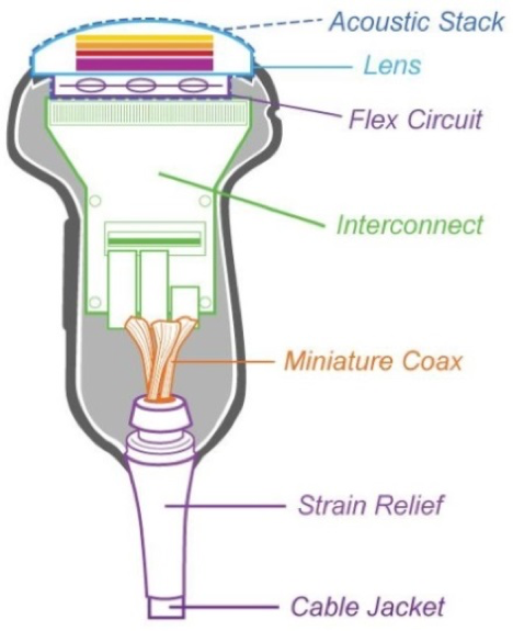
Lens
Matching layer(s)
Acoustic Array
Shielding
Backing material
Flex circuit
Interconnect/Scanhead electronics
Miniature coax
Strain relief
Cable jacket
Main cable
Ultrasound Probe Quality Assurance testing on transducers is a key contributor to improving the accuracy of patient diagnoses, treatment plans and ultimately patient outcomes.
Routine – and consistent – testing is vital to ensuring that devices are performing at a level very similar to that when they were purchased.
By following these best practices, you’ll be able to feel confident in equipment quality. The following can be considered a baseline for beginning the QA process.
System and environment
Testing devices
Consistency between testing is key
Suggested presets
Linear probes Vascular preset
Curved probes Abdominal preset
Endo-cavity OB present
Sector Cardiac preset
Brand specifications
Philips THI, SonoCT and xRes
Siemens THI, MultiHz and SieClear
GE Octave, Crossbeam and CHI
Acceptance testing should be performed when:
Visual inspections should be conducted by sonographers daily
Lens Holes, cuts, missing sealant, bulges, air bubbles, separation in materials
Housing Cracks, separation, missing sealant, sharp edges
Strain reliefs Separation from housing, cuts, holes, excessive stiffness
Cable Cuts, holes, exposed wiring, roll-over damage, excessive stiffness
Connector Deformations, cracks, missing/malfunctioning hardware
Pin-bank Bent pins, corrosion, burn marks, excessive dust/debris
The following are instructions on how to conduct common functional tests required for accreditation.
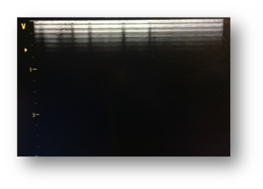
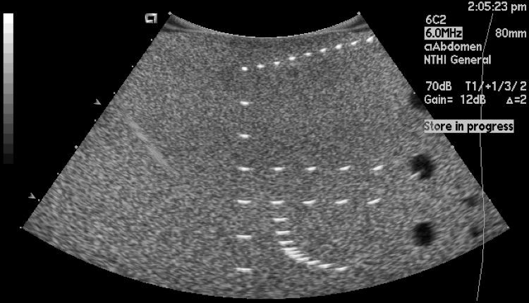
Image Uniformity
Common names
Element testing, channel testing
Purpose
To perform element-to-element or channel-to-channel comparison
Region of interest
The entire width of image
Scanner settings
Frequency Highest possible
Depth 3-6 cm of depth
Focus Single focal point located in the very near field
Gain Adjust overall gain and TGC so that mid-range gray level exists over the entire image
Recommended testing method
Visual criteria
Use the following information to determine next steps for service:
Fine shadow on a single channel: Minor flaw
Multiple fine shadows or wide shadow on multiple channels or elements : Major flaw
Ranking and action levels
| Ranking | Visual criteria | Potential impact | Action |
| 1 | No flaws are present | Operating as expected | No action required |
| 2 | One or two minor flaws are present | Considered operational and can be used for scanning | Inspect occasionally for possible additional deterioration over time |
| 3 | Three or more minor flaws are present | Borderline based upon location | Replace as soon as convenient |
| 4 | Major flaws are present | Unacceptable for clinical use | Remove from service immediately |
Potential root causes for the artifact
| Probe | Root cause/Troubleshooting |
| Acoustic lens | Lens delamination: wide shadowing |
| Acoustic array | A single or multiple missing or weak elements may show small artifacts |
| Cable/wiring harness | Test for intermittencies |
| Pins/connector | Inspect regularly: clean dust from pinned connectors, clean pin-less connector interfaces |
| System | Root cause/Troubleshooting |
| Connector board | Inspect regularly: Examine for damaged pins. Clean dust from scanner ports. Test the probe on multiple ports. |
| Front-end board | Test the probe on another scanner to rule-out a probe/connector issue. |
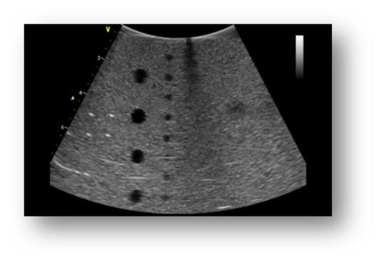
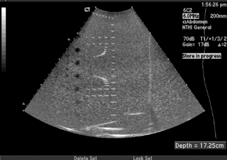
MaximumDepth of Penetration and Functional Resolution
Common names
Maximum visualization, relative penetration or functional resolution
Purpose
To provide an indication of overall sensitivity of a scanner/transducer to detect weak signals
Regions of interest
Fiber targets Maximum depth
Anechoic targets Functional resolution
Scanner settings
You must use same preset for each individual probe model and same model phantom.
Frequency Typical for the probe model
Depth Probe dependent
Focus Adjusted to meet needs
Maximum Depth of Penetration
The maximum distance between the top of the image and the deepest vertical target that can be visualized
Recommended testing method
This distance should remain consistent over the life of the probe
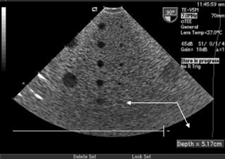
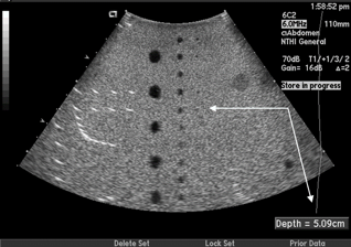
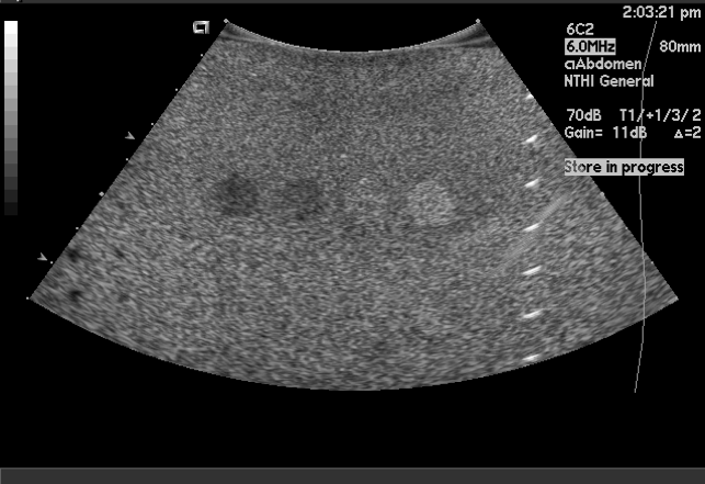
Functional Resolution
The maximum distance between the top of the image and the deepest and smallest anechoic target that can be visualized.
Recommended testing method
This distance should remain consistent over the life of the probe
Ranking and action levels
Potential root causes for a change
| Probe | Root cause |
| Acoustic lens | Lens thickness: improper repair |
| Fluid/gel infiltration | |
| Damage to matching layers | |
| Acoustic array | Arrays can degrade over time (>8-10 years) |
| System | Root cause/Troubleshooting |
| System | Inconsistent preset |
| Display settings |
| Environmental | Root cause/Troubleshooting |
| Environmental | Ambient lighting |
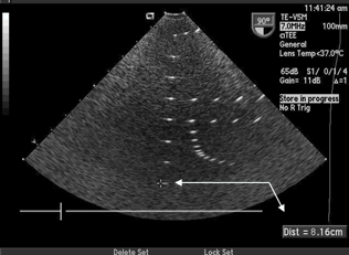
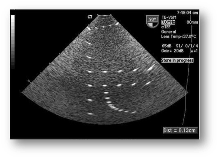
Geometric Accuracy
Common names
Purpose
To verify both horizontal and vertical accuracy
Region of interest
Respective target groups
Scanner settings
Frequency Typical for the probe model
Depth Probe dependent
Focus Single focal point located in the center of the area to be measured
Vertical measurement
Verify that the target distance is with 1.5% or 1.5mm (whichever is greater)

Horizontal measurement
Verify that the target distance is within 2% or 2mm (whichever is greater)
Potential root causes for inaccuracies
| Probe | Root cause/Troubleshooting |
| Acoustic lens | Lens thickness, lens material: improper repair |
| Compare measurements between multiple probes of the same model |
| System | Root cause/Troubleshooting |
| System | Gross inaccuracies may indicate a major system issue |
| Compare measurements between multiple systems of the same model |
Spatial Resolution
Common names
Purpose
To verify the minimum distance at which two targets can be individually visualized
Region of interest
Scanner settings
Frequency Typical for the probe model
Depth Phantom dependent
Focus Single focal point located in the center of the area to be measured
Lateral resolution (X)
Axial resolution (Y)
Elevational resolution (Z)
Recommended testing method
The distance should remain consistent over the life of the probe
Potential root causes for changes
| Probe | Root cause/Troubleshooting |
| Acoustic lens | Lens delamination |
| Lens thickness, lens material: improper repair | |
| Compare measurements between multiple probes of the same model |
| System | Root cause/Troubleshooting |
| System | Improper focal point location |
| Gross inaccuracies may indicate a major system issue | |
| Compare measurements between multiple systems of the same model |
Contrast Resolution
Common names
Gray scale, gray scale resolution
Purpose
To provide an indication of the system’s and the probe’s ability to distinguish between objects of similar and varying densities
Region of interest
Gray scale targets
Scanner settings
Frequency Typical for the probe model
Depth Dependent upon phantom model
Focus Positioned at or right-above targets
Gain Adjust overall gain and TGC so that mid-range gray level exists over the entire image.
Recommended testing method
The targets should appear circular in shape and vary in the degree of brightness ranging from low to high levels of contrast
| Probe | Root cause/Troubleshooting |
| Acoustic lens | Lens thickness: improper repair |
| Fluid/gel infiltration | |
| Damage to matching layers | |
| Compare results between multiple probes of the same model | |
| Acoustic array | Arrays can degrade over time (>8-10 years) |
| System | Root cause/Troubleshooting |
| System | Inconsistent preset |
| Display settings |
| Environmental | Root cause/Troubleshooting |
| Environmental | Ambient lighting |
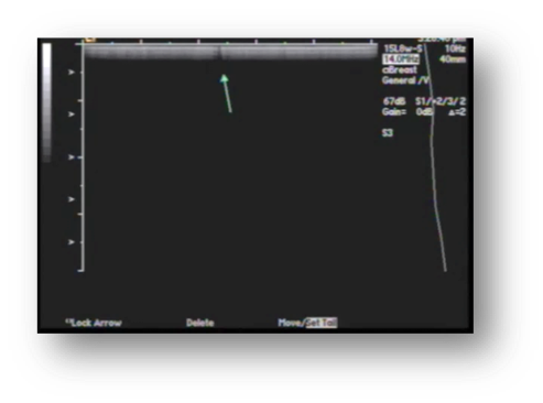
Cable Noise Test
Purpose
To identify intermittencies and breakdowns in signal wiring in the cable harness
Region of interest
Entire width of image
Scanner settings
Frequency Typical for the probe model
Depth 6-8 cm
Cardiac probes CW Doppler mode
Non-cardiac probes Color Doppler mode
Recommended testing method: cardiac probes
Recommended testing method: non-cardiac
Potential root causes for artifact
| Probe | Root cause/Troubleshooting |
| Wiring harness | Intermittent wiring: Heavy static sounds in CW mode, streaks of flashing color in color mode |
| Major wiring damage: intermittent dropout in the 2D imaging |
Electro-mechanical Functionality
Purpose
To identify electro-mechanical failures in 3D/4D volumetric probes
Region of interest
Scanner settings
Mode 3D/4D
Recommended testing method
Potential root cause of failure
| Probe | Root cause/Troubleshooting |
| Probe | Impact to dome: internal electro-mechanical damage |
| Motor failure | |
| Sensor failure |
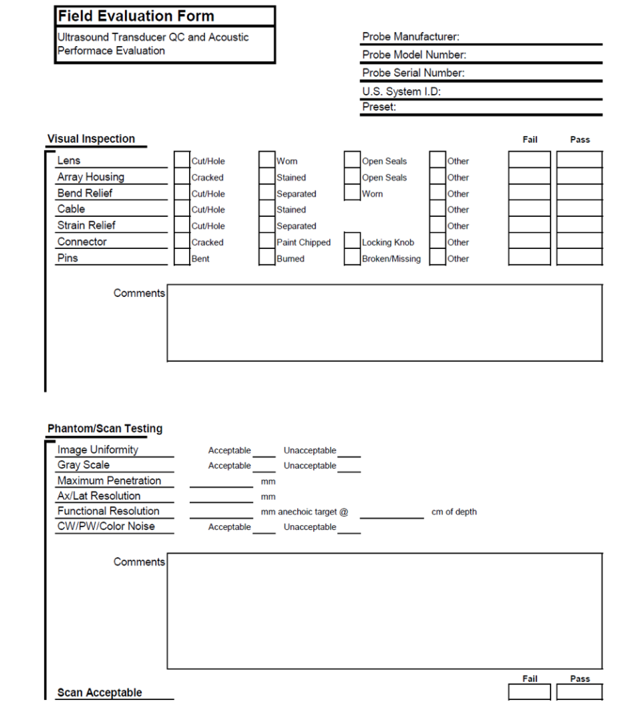
Currently, there is no standardized form within the industry for documenting Ultrasound Probe Quality Assurance or system performance. Below is an example of a form which can be created using Microsoft Excel. Our team can help to customize a form to meet your needs.
I have a question regarding on how to take the geometry accuracy measurement or a true distance in Axial and lateral my question how do you take the reading. If you can help me on that I appreciate it.